
Making a Better Planet to Live in by Plummeting Greenhouse Gas Emissions Monetizing Gas Flare with Plug-and-Play-Solutions
- Published on September 9, 2020
By Roberto Saldano – Director at Casius Consulting
Introduction
Given the seriousness of climate change, gas flaring is one of the major environmental concerns facing the world today, causing a significant amount of Greenhouse Gas (GHG) emissions that contribute to the overall burden of global warming and have harmful effects on health, noise/air pollution and well-being of local communities.
Gas flaring is a combustion of associated gas generated during normal or unplanned over-pressuring operation in well-sites, oil & gas processing facilities, refineries, chemical plants, coal industry and landfills. Due to flaring being a waste disposal process, there is no systematic reporting of the flaring locations and flared gas volumes. Typically, the flare volume reports are estimated by operators from the difference between the natural gas volume produced and the quantity used in the process or sold.
This article highlights, first, a systematic approach to global gas flaring estimation, second, to point out the technologies needed to achieve “Zero Routine Flaring by 2030” are already available, however, it can only be achieved by doing a fundamental change in our behaviors, deploying plug-and-play-solutions such as the conversion of gas into power, or Liquefied Natural Gas (LNG) or Compressed Natural Gas (CNG). Third, reducing the environmental impact by capturing flared gas presents an opportunity to create new value chains that can benefit not only the industry’s social license to operate and care for the environment, but also improve the quality of the communities’ life.
Gas Flaring Estimation
The Global Gas Flaring Tracker report issued on an annual basis, published on July 2020 by the World Bank-managed Global Gas Flaring Reduction Partnership (GGFR)1, which comprises governments, oil companies, and international institutions working to end routine gas flaring at oil production sites around the world, highlighted that in 2019 gas flaring has increased to levels last seen in 2009—a full decade earlier.
According to The World Bank’s Global Gas Flaring Reduction Partnership, the gas burned worldwide was 150,000,000,000 m3 of gas in 2019, the equivalent of more than 400 million tons of CO2 and comparable to the total consumption annual gas from sub-Saharan Africa1.
To determine the flare volumes from satellite data, The World Bank’s Global Gas Flaring Reduction Partnership (GGFR), in partnership with the U.S. National Oceanic and Atmospheric Administration (NOAA) 2 and the Colorado School of Mines, have developed global gas flaring estimates based upon observations from a satellite launched in 2012. The advanced sensors of this satellite detect the heat emitted by gas flares as infrared emissions at global upstream oil and gas facilities. The amount of heat generated is close to proportional to the volume of gas being burned. The heat, in the form of infrared emissions received from a flare by the satellite, generates a signal with a unique temperature and magnitude are used to estimate the radiant heat being emitted by the flare (in Watts). The Colorado School of Mines and GGFR quantify these infrared emissions and calibrate them using aggregate country-level data collected by a third-party data supplier, Cedigaz, to produce robust estimates of global gas flaring volumes.
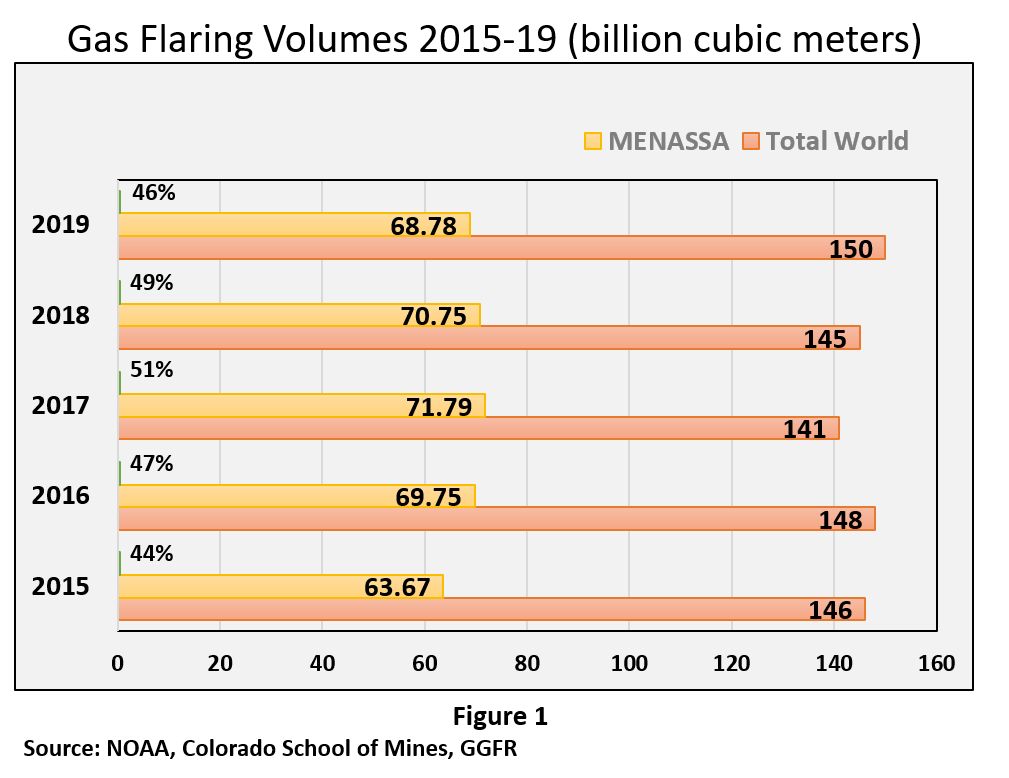
The Middle East, North and Sub-Sharan Africa region in 2019 accounts by 46% of the world’s gas flaring with 68 billion cubic meters, as shown in Figure 1.
These emissions come from the routine gas flaring at oil production facilities during normal production operations in the absence of enough facilities capacity or amenable geology to re-inject the produced gas, utilize it on-site, or dispatch it to a market. Other sources of gas flaring are due to ensure safe operations of the facility such as blow-down gas following emergency shutdowns to prevent over-pressurization of all or part of the process systems or gas required for a flare’s pilot flame.
SkyTruth.org flaring map shows the heatmap of night time Middle East, North and Sub-Sharan Africa, based on the infrared satellite detections of natural gas flaring across the entire planet, as seen by the VIIRS instrument aboard NOAA’s Suomi NPP satellite(3). Typically, the single-day view is used to see the gas flare detected on a specific date, and the multi-day composite to realize how frequent the flares were over a few weeks or a month. Figure 2 shows the flaring gas location of all detections over 20-day periods between Aug-03-2020 and Aug-23-2020. The map displays all the flares detected on the date displayed.

Plug-and-Play-Solution
Proven technologies, mobile, portable and scalable plug-and-play solutions that reduce foot print areas and shortening execution time, are endorsing decision makers to quickly monetize flared gas, benefiting all stakeholders such as the environment, governments, oil and gas industry, job creation, communities and development institutions.
The flow scheme shown in Figure 3, is the mobile, portable and scalable solution to handle the sour gas flared at the well-site in most of the Middle East Region—the first stage is removing H2S. Portable treatment units through self-regeneration systems are available on the market for the removal of H2S in concentrations up to 20 Tn/day of Sulphur, at a very competitive cost. The resulting product of these units is a wet elemental sulfur cake that can be deposited in landfill sites. (4,5)
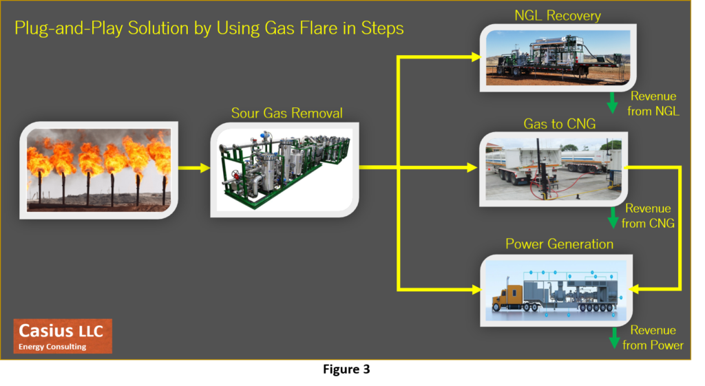
Then, moving to the second stage, three technologies will be assessed.
1. Through liquefaction technologies, small-scale Liquefied Natural Gas (LNG) reduces the size of gas volume by 600 times, allowing gas transportation in trucks equipped with cryogenic ISO tanks. Due to minimization of dynamic components, use of fluids and labor facilitate an uptime operation over 90%, running entirely unmanned, 24/7 monitored remotely through SCADA Systems. The setup provides multiple layers of integrated safety procedures and automatic shutoffs.
Scalable installation capacity allows to increase in-demand by incorporating units progressively; trailer-mounted units cover a range from 300 MCFD to over 12,000 MCFD6.7. These elements can be used for communities injecting into natural gas grids or LNG terminals. LNG stations are the most convenient clean fuel for long distances and high-level demands of gas in a short period of time.
Thus, it directly connects gas sources and communities, benefiting from a clean fuel LNG, at a competitive cost. This solution is a true game-changer to monetize resources that have value but are now nil and cause immense damage to the environment.
2. Compressed Natural Gas (CNG) is another viable solution to monetize volumes (1-15MMscf/d). CNG is transported and stored in compressed forms (pressurized between 100 and 250 Barg units) in order to reduce the volume to be transported or stored by between 150 to 300 times that of gas at atmospheric pressure.
CNG on-shore is a proven gas transportation technology that has been around for decades and has been encouraged since 1990 as a vehicle fuel. CNG transportation from truck loading from well sites to truck offloading at consumer site. Various CNG bulk transport systems are used by energy and technologies companies promoting virtual pipelines associated with clean fuel usage6. CNG technology is a cost-effective solution to supply gas to areas which are not reached by the grid and do not reach the minimum required volume to invest in a traditional infrastructure.
The economics of CNG projects depend on the conditions of each one, it is generally subject to the volumes delivered, the distances to the market impacting the transportation, which is the most important factor in CNG chain costs, loading and offloading facilities that would need to be built. In the other side, pricing also varies whether the CNG is delivered to a gas pipeline or to an independent power supplier.
3. Gas-to-power conversion technology involves the use of gas as a fuel source for generating electricity through a turbine. This technology could be achieved through two main ways, namely combined heat and power (CHP) and combined cycle gas turbine (CCGT).
Field power technology has evolved, supplying in remote locations and trailer power in industry. The single trailer design is a complete mobile power plant with wide fuel composition flexibility, shortest set-up time, not involving crane lifts, allowing for easier coordination of installation and relocation. 8
Gas turbines may be built small or large, with different plant configurations, can be flexibly based on demand ramped up or down. Several applications in the oil and gas fields have been deployed over the years, from the capture of gas flares that is the goal of this analysis, but also in fracking operations, drilling and completion of wells, gathering and processing systems, oil field operations, and microgrids.
One of the solutions is to develop large gas markets with the intention of end-use applications such as power generation. Another alternative solution is to pursue smaller-scale gas uses near to the source by building scalable, mobile gas power plants to supply power for oil field operations, local industrial uses, residential networks, or injection into the grid.
Economics of Gas Flaring
It has been extensively described that gas flaring is a form of waste of natural resources and carries enormous economic impacts, losing billions of dollars annually in revenue generation. Furthermore, in regions such as the Niger Delta of Nigeria, it has created enormous problems of soil infertility and the livelihoods of local farmers.
By contrast, several analyses performed by independent consulting services in various fields found that flared gas recovery projects offered substantial economic and financial returns even without carbon-reduction credits and other fiscal incentives. Several investment projects are under development, some of them are oriented to use of gas for power and others in Gas Lift, reinjection and as fuel for field uses.
In conclusion, the decision to invest in a certain technology can be challenging, due to many factors such as strategy of investing companies, capital investment, technology risks, domestic market structure, distance to market, environmental policy, existing infrastructure, etc., need to be considered by the decision makers.
Conclusions
The global trend over the years regarding associated gas flaring and venting in production fields has confirmed the need to renew the commitment to an aggressive mitigation plan. Regardless of who is flaring gas, whether it is a NOC or IOC or independent, incentives for investment in reducing gas flare must be established, encouraging buyers and sellers willing to make beneficial economic use of large volumes of gas flared each year.
No single option is best for all oil fields, since each field has its own characteristics, size, local market conditions, and each country has its own political, institutional and financial framework. Therefore, a specific assessment of available technologies and alternatives is highly recommended to select the best practice.
The technologies required to reach the “Zero Routine Flaring by 2030” are available and ready to be deployed, it requires determination to use them at a faster pace and scale, committed by the local environment, public health and investors financing lower carbon emitting projects.
References
1- Global Gas Flaring Tracker Report, July 2020, World Bank.
2- World Bank’s Global Gas Flaring Reduction Partnership: Gas Flaring Estimates – Methodology for determining the flare volumes from satellite data.
3- SkyTruth Satellite-Detected Natural Gas Flaring.
4- Sulfatreat, Schlumberger
5- GTUIT, GPUR H2S treatment equipment
6- Galileo Technologies
7- GTUIT
8- Solar Turbines, Caterpillar
Fit-For-Purpose Surface Facilities De-risking and Adding Value in O&G Asset Planning
- Published on July 22, 2020
By Roberto Saldano – Director at Casius Consulting
Greenhouse gas emissions have been growing accelerated over the last two decades, therefore climate concerns are pressing and decarbonization objectives have become more ambitious, nowadays many oil and gas ventures compete with renewable energy for funding, but the existing trend has been exacerbated due to COVID-19 pandemic and lower-oil-prices. Energy enterprises are forced to design oil and gas developments geared toward sustainable direction, detailed planning, lean execution with greater certainty about budget, schedule targets and backed by crucial technologies that are more mature, competitive, and scalable.
This article examines the conceptual stage or pre-FID initiatives through a case study, since this is the time where the least money is spent, but where the project team has the greatest influence. Corporate management has driven dramatic cuts in project team capacity and increased pressure on suppliers to reduce costs, even in a market where margins have been extremely low. The leadership mindset and initiatives must now more than ever enhance performance and build sustainability by reducing inefficient interactions, accelerating schedules to get early-cash-in by bringing in the first oil, seeking to share risks, share global and local experience with service or technology providers, and incentive mechanisms in contracts.
Asset development management has been formalized in an investment governance and project approval process, a structured approach to planning, executing development and committing investments has increasingly been adopted. Figure 1.
All evaluations will have a level of uncertainty associated with them. The progressive evaluation stages are designed to forecasting the asset performance and to evaluating the associated risks with the mitigation strategies.
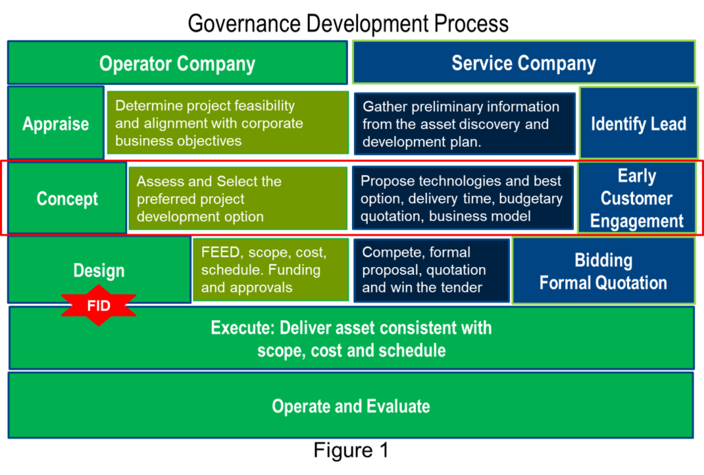
The appraisal stage to determine that the project is technically, operationally and commercially feasible, and that it is likely to fit into the corporate objectives. i.e.: a small heavy-oil resource in deep water may not attract corporate commitment if a shallow onshore development is also competing for investment of capital and resource.
As part of the pre-sanction activities, the conceptual engineering to evaluate the different development alternatives or concepts. What are the relative merits and risks of sub-sea development, versus platform development, versus artificial island development. These high-level evaluations will determine the scope of work, the reserves to be developed, the production profiles and the cost.
On the other hand, from the perspective of service or technology providers, this phase known as early-customer-engagement allows to de-risk of asset planning by evaluating technologies, recommending ways of execution, estimating delivery time, brainstorm comprehensive risk assessment and discussing the business model. Also, the service provider will decide to pursue this opportunity to fund resources and budget.
Design phase, once a preferred alternative is selected, a more detailed analysis needs to be conducted in order to deliver more resolution on the development and production profiles, secure corporate, regulatory and financial approvals and to deliver detail tender packages, procurement specifications and project plans. This phase end sanctioning the project final investment decision (FID).
Execution is to effectively manage the construction of the production system, drill and complete the required wells and commission the system. This phase is where the major capital expenditure occurs.
Last phase, operations to effectively and efficiently operate the asset to ensure project targets are met, exceeded and maximize the returns to the stakeholders.
Concept stage: The role of Petro-technical staff (reservoir engineers, geologist and geophysics), drilling, production, facilities engineers, and accountants in an upstream organization is fundamentally to determine the forecast production from the asset, to operate and manage it to meet and exceed forecast, to determine the associated risks and mitigation strategies and the asset economics.
Technical evaluations are undertaken to do this. Using physical and engineering principles to envisage an asset performance using appropriate tools and analysis is the most effective and reliable methodology to do this. It is also important to recognize that stakeholders, investors and legislative bodies are also looking for the credibility that expertise and industry recognized technical evaluations bring.
Pursuing for technological solutions by operators and service companies for optimizing production infrastructure designs, surface processing facilities, hydrocarbon export management, greenhouse emissions reduction, whilst digitalization is embedded through overall scheme. Adopting standardization by developing standard project design templates, project management methodologies, engineering workflows, and designs enables to reduce variation in delivery performance, improve efficiency in rapid-response, and simultaneously optimize costs of equipment and technology. On the other hand, due to the severe and brutal reductions in the budgets available to energy enterprises, the introduction of debates on business models and a high-level framework for contracting that is feasible for both parties is essential.
From a predominantly surface facilities perspective, there are a number of key areas of technical evaluation that will be carried out in the conceptual engineering phase.
Technical evaluations on concept stage: With increasing gas demand for infrastructure and energy needs, the pursuit of gas development persists throughout the Middle East region with the recovery of sour oil and gas fields gaining priority in many countries.
Solutions usually begin by sharing data between operators and service providers, technology solutions must understand customer needs, context, risks, environment, priorities and limitations, deadlines, quick wins, and both must speak the same language.
On this particular prospect, the gas field development plan is a show-case, the Operator intends to install an onshore gas treatment plan, the nominal capacity is 180 MMSCFD, it should be able to receive a maximum expected hydrocarbon liquid flowrate of 10,000 BOPD and produced water of 15,000 BWPD. Foot print of the gas treatment plant shall be minimized while always respecting compliance with HSE requirements.
Well Fluid Composition is provided, it represents the mixed stream coming from Production manifold and entering the Low-Pressure Separator at 7 barg Summer and 17 barg Winter cases from the Clusters. Environmental design data, soil characteristics, country laws, rules and regulations are established, the International codes and standards shall be applied to the project (ASME, API, IEC, NFPA, etc.), and the design life of the facility is 20 years. Gas treatment plant shall include utilities and ancillaries to guarantee a stand-alone operation. The rich CO2 gas stream will be disposed by injecting into reservoir wells.
The service company will advise a solution of technological options, including Capex, Opex, delivery-time and compliance with the requested process performance.
Historically, CO2 removal in natural gas streams has been accomplished using amine systems, however, over the past twenty years membrane systems have gained remarkable traction in this market segment. So, these two proven technologies have been the evaluated options for this particular opportunity and the comparison of them as well.
Aspen HYSIS has been used to process simulation, which provides the chance to estimate physical properties, liquid vapor phase equilibrium, material and heat balances.
Amine System: The separated raw gas stream is compressed and sent to the other higher-pressure gas processing sections, Mercury Removal unit, Gas Sweetening unit, Gas Dehydration/Dew Point unit. Figure 2.

Treated gas outgoing the Mercury Removal Unit (non-regenerative type) is sent to the Gas Sweetening unit (amine type) to remove CO2, and then it will be cooled down to feed the Dehydration/Dew Point Control section (chilling system) in order to separate the condensate from the gas and reach the required Sales Gas specification.
Part of the treated gas will be used as a fuel gas in the gas treatment plant in the new Power Generation system.
The stabilized condensate bottom stream is sent to export pipeline, while the overhead stream will be recovered and sent to the Sales Gas Compressor or used as fuel. The liquid C3/C4 separated from the Stabilizer overhead will be pumped into the export gas pipeline.
The rich CO2 gas stream from amine regeneration will be disposed by CO2 injection into reservoir wells in a phased approach (to be confirmed), then provision for CO2 injection compression system shall be foreseen in Gas treatment plant layout.
Membrane System: The separated raw gas stream is compressed and sent to the other higher-pressure gas processing sections, Mercury Removal unit, Gas Sweetening unit, Gas Dehydration/Dew Point unit. Figure 3.
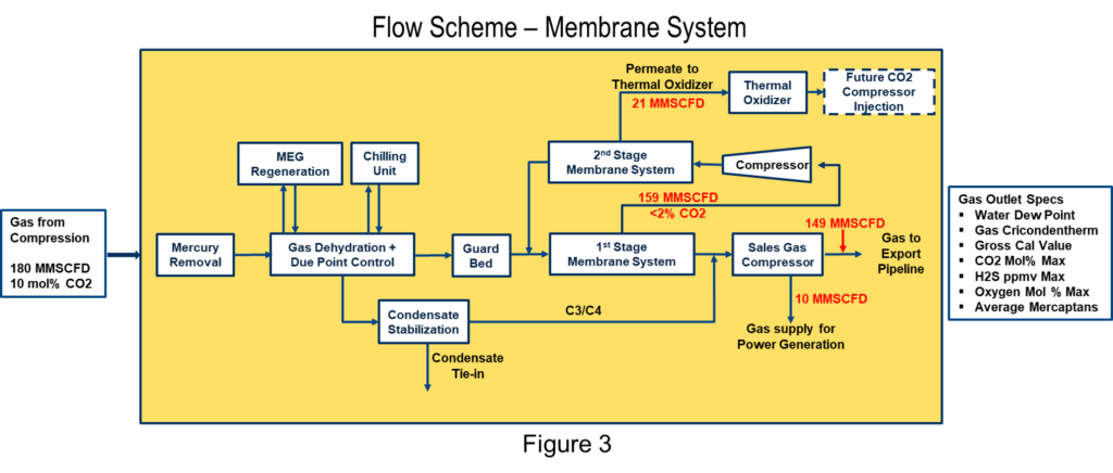
A two-stage membrane system has been selected to allow greater CO2 removal in the permeate stream and maximum hydrocarbon recovery to the sales pipeline, however this configuration requires recycle compressor. As the gas travels between membrane sheets, CO2 and H2O permeate through the membrane and are collected in the permeate tube, then the permeate stream of the first membrane serves as feed for the second membrane.
Comparison Systems: Based on the technical analysis conducted and clarification received from customer, the factors summarized in Table 1, it can be used to finalize a preliminary technology selection.

§ For Total Capex (Equipment + Installation), do not see any difference at this stage for either of the options.
§ For Annual Consumable costs, similar for both options due to costs of solvent replacement is offsetting with replacement frequency of membrane elements and recycle compressor.
§ It is not feasible at this stage of inquiry to have further accuracy, than what has been presented.
§ Regarding configuration of Amine system, it will be based on 2 trains due to the size of regeneration system, this will allow us to modularize/package majority of the system which will provide advantage in shipping & installation time. However, the amine contactor and few other equipment can be made common after further evaluation. Full definition of this configuration will be confirmed during the tendering process.
§ The membrane housings are a critical component of the CO2 membrane system have to be supplied from the manufacturing that need to be approved by customer.
§ Keeping in view the high priority for delivery timeline, no limitations in terms of origin of material and fabrication is required.
§ Whilst membrane systems seemed attractive, however a more detailed analysis of all aspects of design, installation and operation, results in an Amine system being competitive as well, further study is needed to recommend the best option.
Schedule estimation: There are several different tools to choose from, the project can be broken down into three main groups such as engineering, procurement, and construction. In this stage of the project, the most important events that mark the critical path of execution are highlighted, critical activities such as technical requests (TR) are established that trigger the supplier quotes to place equipment purchase orders (PO). On the construction side, prefabrication in the workshop, mobilizing the camp, and installing civil foundations, mechanical, electrical and instrumentation make up the puzzle to achieve the first gas. Figure 4.

Risk Schedule: Scheduling risks arise due to uncertainties in the overall project execution, usually carried out one day multi-disciplinary workshop to brainstorm a risks identification and mitigation plan. The outcome of this type of activity is shown in Figure 5.

Costs estimation: Cost estimates can be prepared in a number of ways and levels of detail that influence accuracy. The Association for the Advancement of Cost Engineering (AACE), Recommended Practice No. 18R-97, for engineering, procurement, and construction for processing plants, provides expected accuracy range that may be assigned to an estimate at any given stage of a project. Figure 6.

Typical accuracy ranges for Class 4 estimates are -15% to -30% on the low side, and +20% to +50% on the high side, uncertainties will be clarified as the project matures, such as soil properties, site preparation, fluid properties, tie-in orientation, interfaces, sparing philosophy, and project-specific risks (i.e.: events and risk conditions), etc.
Once documents from engineering are available, such as equipment list, weight, and dimensions, typical data sheets, process flow diagrams (PFDs), lay-out dimensions, major equipment and utilities will be manufactured on-skids. These deliverables are taken by a multidisciplinary team of project services, engineering and supply chain to define the source of supply and build the breakdown of costs, therefore clear methodology and templates are required to streamline the exercise, generally it can be use 3 main groups:
§ Engineering and project management team, the staffing plan for similar projects is taken as a reference, however costs are customized according to the country where the project will be executed.
§ Equipment costs of comparable executed projects are taken as reference, national and international logistics, customs clearance, etc., are included.
§ Construction contractors and bulk materials as piping, structural, cables, civil foundations, off-skids instruments, camp and personnel’s transportation, catering, etc.
Site preparation and civil works are generally not included due to the high level of uncertainty; however, operators are encouraged to initiate geotechnical and topographic studies to provide greater certainty and give more confidence to project execution and even to reduce contingency in pricing at the tender stage.
This group of costs are managed locally by efficiency and are affected by local regulations, summer and Ramadan season, night work, double shift, etc.
Risk Costs:Budgeting risks arise due to uncertainties in the overall project execution, risks identification and mitigation plan begins with a multi-disciplinary approach to early facility design planning. Typical top risks identified in a workshop session is shown in Figure 7.

In Conclusion
To accomplish higher levels of efficiency and performance, oil and gas organizations are encouraged to lead a significant cultural change in the way operators, service companies, major providers and EPCs achieve greater collaboration and alignment. By working together, these players will also improve standardization across the industry, which has yet to gain significant momentum.
Pre-sanction initiatives at conceptual stage allows to de-risk and add value to the asset planning, by evaluating technologies, accelerating schedules to get early-cash-in by bringing in the first oil, building a comprehensive risk assessment, discussing the business mode and planning lean execution.
Engineering Optimization for Production Facilities Enabling Safe Operations and Cash Flow
- Published on July 9, 2020
By Roberto Saldano – Director at Casius Consulting
The worldwide shock caused by the coronavirus (Covid-19) pandemic has drastically altered the course of the global economy and energy markets, exposing and reinforcing the need to create business models more dynamic, integrated and based on risks. The oil and gas industry has undergone a major transformation in the way it operates, with greater focus on activities offering paybacks in a shorter period of time and the sanctioning of simplified and smaller projects, in which a modular approach allows to increase the capacity of the facilities according to the market demand.
This update is aimed to give certain insight into how fast-paced engineering can be capable of maximizing value for both the customer and service provider by earlier cash-in due to accelerated production, lowering the overall barrel cost produced, and potential reduction of greenhouse emissions, throughout the Processing Systems Technologies and Production Facilities.
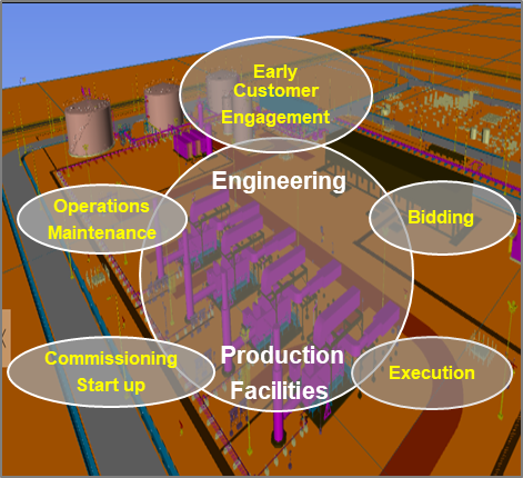
The framework of this article is that the Service Company acts as a technology and solutions source for Independent, NOC, IOC, by introducing innovative and cost-effective technology solutions managing a comprehensive list of project risks. It pursues to maximize overall performance throughout full life cycle by long-term engagement, since early customer engagement, bidding, execution engineering enabling manufacturing, construction, commissioning, and to end operations and maintenance.
Early Customer Engagement: solutions usually commence by being curious with the customer, understanding their needs, context, risks, environment, priorities and limitations, deadlines, quick wins, and speaking to them in their language.
It is a vital stage for aligning goals and expectations, it pursues to identify how to create value for customers, mastering the customer journey, towards the end-to-end customer experience and giving advise into shared value creation. It fits into the customer’s FEED stage, processing technologies and innovative ways of execution are evaluated, and the best solution is found aligned with the customer’s corporate goals. The criticality of getting this right is evident in the plot shown below. Under-estimate or over- estimate the design requirements at the outset, and no matter how well you execute and operate, or how much capital you throw at the opportunity, you will never realize the value potential.

Careful evaluation of the technology, suitable engineering design and sizing of facilities, execution scheduling and provision for formalized risk contingencies define the project. Getting this project definition right is therefore paramount to reach sustainability. Furthermore, for de-risking project opportunity by minimizing execution uncertainty and influencing customer requirements and specification changes, towards more achievable goals, with the necessary balance between investments and risk.
High level project and processing technology description, simulations, heat and mass balance (H&MB), process flow diagram (PFD), availability and reliability considerations, safety strategy, preliminary equipment list, budgetary quotation, and estimated delivery time, are the list of documents delivered to the customer at this stage.
Bidding: it’s about beating the competition, being able to build a team spirit to brainstorm, make connections with lessons from past projects, careful assessment by experts in the oil, gas and water processing systems technologies and select the case solution, conduct process safety analysis, and constructability, operability and maintainability reviews of the facility.
The engineering and design of production facility is a complex team effort involving different disciplines of engineering: process, mechanical, piping, electrical, instrumentation, controls, materials, safety, and project. The structure of the project engineering team is desirable to remain steady during the bidding and execution phase. It also entails considerable management skills and coordination despite time zones difference, geographical dispersion, and nationalities, always managed with a team spirit to achieve the committed objectives.
The mindset of the engineering team to outperform the competition through a clever and cost-effective solutions follows some guidelines but are not limited to this:
Processing Technology: a systematic assessment of processing technology for separation, dehydration and desalination of oil, gas, water, and solids handling will depend on whether it is light or heavy oil, sour oil, or sour gas, is the gas reinjected? Is the water treated, reinjected? What will be the handling of solids? What are the output specs for oil, gas, and water? What is the target specs for each stream? etc.
Therefore, the multidisciplinary engineering experts to drive the technical complexity and find the fit-for-purpose-solution. The design phase starts with the Process Simulations, Heat and Mat Balance (H&MB), Process Flow Diagram (PFD) and client specifications given into Invitation to Tender (ITT). The outcome of the design phase is usually sizes of major equipment, data sheets and P&IDs associated, always applying process safety analysis in accordance with type of installation across the design life cycle.
Modular Engineering at bidding: modularization, which entails prefabrication and preassembly of structures away from the construction site, it comes in various sizes, loads, and shapes, from very large modules that are transported by barge, trucks, and sometimes modules that may fit in a sea freight container. This concept is really important to optimized resources, investment and made a viable project.
Modular execution provides benefits by improving quality, delivery time and labor productivity, due to better controlled working and fabrication conditions, i.e.: the risks of working at height and of mechanical lifting are reduced, and risks to health, even to safety and the environment (HSE), are minimized.
A well-developed modular-execution strategy creates an integrated solution for projects in remote areas, severe climatic conditions, or a shortage of skilled labor. Lego and Plug-and-Play approach are leading the way to improve overall project results, engineering efforts associated with modularization must be technically sound and achieve the requirements that are expected for a facility to operate safely, deliver the specified product, and achieve the target production.
Whether Process skids or facilities, in both cases engineering is expected to design the construction phase as its client; that is, designing a facility so that it is easier for the construction group to build that design in the field.
The solution engineering also addresses a careful weight management to control module size and minimize any shipping and installation surprises.
Lay-out Optimization: a cost-efficient and inherently safe layout can be provided in the early stage of the production facility design. Engineering and design aimed at the shortest construction times and putting the plant into operation as quickly as possible.
Project data such as location, local codes and regulations, access roads, waterways, railways, seismic conditions, climate data (average temperature, and rainfall), wind speed and direction, inlet and outlet tie-ins are key inputs to developing a tailor-made plant layout that ensures a compact configuration for economic efficiency.
Guidelines must follow such as proper safety distance involving flare stack location with the associated thermal radiation, noise, and air pollution impact, even safe separation between process equipment and/or process systems, determined for specific operational conditions and particularly barriers like SDV, F&G, etc. Constructability review to save time and money by uncovering problems or potential problems that may be faced during construction such as errors, omissions, ambiguities, and conflicts. Operability, sufficient working space, and headroom must be provided to allow easy access to equipment. Maintainability, space for maintenance i.e.: heat exchangers need to be sited so that the tube bundles can be easily withdrawn for cleaning and tube replacement. Flexibility is key to take care of probable future expansions.
Uni-direction flow move only in the forward direction, toward stage of completion, area for processing such as slug catcher, three phase separation, treatment package equipment of oil, gas, and water. Pumps for oil export and water injection located as much as close to power generation, area for storage, compression, utilities, buildings, and roads.
The Process Flow Diagram (PFD) and preliminary Piping & Instrumentation Diagram (P&ID) are developed by process engineers and reviewed, completed, and discussed by the project engineering disciplines in order to ensure proper, efficient and safe operations. The P&ID contains details and specifications of all equipment, piping, fittings, instrumentation, control valves, safety elements and contains references to detailed drawings of equipment. The P&ID serves as the primary reference document in communication between engineering and design personnel in all disciplines. Thus, the P&ID is a key working document in the engineering and design of processing plants and piping systems which are connected to technical data such as operational and safety philosophy.
The P&ID, plot plans and elevations are used in building a 3D model of the processing plant, it will cover all the components involving major equipment, utilities, pipe racks, piping, control stations, buildings and support structures. The 3D model will allow for reviews of the constructability, operability, and maintainability of the facility.
Material Take-off (MTO) and installation specs for civil, structural, piping, mechanical, electrical, instrumentation, and control are key deliverables in creating the Bill of Materials (BOM), which is then used to request for quotation (RFQ) for all necessary materials and complete bidding cost exercise.
Risks: It is essential to identify the risks related to possible scenarios in advance and be prepared to implement contingency measures, as needed. An execution risk identification, analysis, evaluation and mitigation workshop are held, involving multidisciplinary team such as designs engineers, customer’s experts and external process risk advisors. Typical engineering risks are late issuance of technical requisitions, missed in engineering, changes due to engineering studies, delay in vendor engineering documents, etc.
Execution: once the contract is awarded, a detailed handover from Sales to Project Execution is carried out, then the project engineering team executes according to the bidding proposal with slight variations, unless the client requests such variations, in that case, will be handled as variation orders (VO) and amended into the original contract.
The organizational responsibilities (RACI Matrix) and scope interface demarcations (Interface Matrix) require to be well defined and communicated to all persons and companies involved in the work. R – Responsible (Does), A – Accountable (Approves), C–Consult (Reviews), I– Inform (Requires being informed).
Custom-engineering-design-strategy is driven by deliveries to speed up design review workshop, technical requisitions moving forward to procurement stage, safety analysis review such as HAZOP, QRA and SIL, site-preparation specs, civil foundation designs with the aim of being ready when modules arrive at site, building the 3D model and issue in 30% of it, first cut of materials take-off (MTO), which will be progressively updated with supplier’s data and feedback of the safety reviews and constructability recommendations. Either International standards (API, ASME, etc.) or customer specs will be followed.
Successes criteria are customized and agreed along with the project team, furthermore best practices suggest that strong customer setup is desirable for regular monitoring and pragmatic decision making at the right time and approval of documents if needed.
Design review at 30% and 60% of engineering are systematic approach exercises that embraces teamwork of construction, commissioning, operations and maintenance, enriching the discussion and making the design more robust. This provides a path to more efficient design by incorporating the teams’ expertise to deliver overall safe and reliable plant operation.
Technical Requisitions: Global sourcing and manufacturing was part of the project execution plan; therefore, critical major equipment will be addressed as a priority. Consolidation of technical data such as data sheets, P&ID, specs, technical narrative, are key to kick-off the procurement phase.
Automation is the main driver in the design and operation philosophy, certain standards have been developed in recent years, to accommodate industry 4.0 principles, big data, ensure consistency among systems when operating and communicating 24 x 7 data. Emergency shutdown and safety instrumented systems are integrated as part of the engineering design.
Efficient-cost global supply and manufacturing create a capital efficiency that allows many projects to be sanctioned that otherwise would not have been able to move forward. End-to-end material management has become a complex, international enterprise, while qualified suppliers ranked by financial capabilities, quality, lead time, cost, and risk are previously assessed.
Safety Studies: HAZID, HAZOP, safety integrity level (SIL), QRA, FERA, RAM, human factors (ergonomic), pre-startup safety review (PSSR) and others are typically the safety studies completed and constructability review (CR) to assess potential hazardous and problematic events to improve construction efficiency. The typical safety study workflow is shown in Figure 2.

The project engineering manager must take proactive leadership by executing recommendations from the approved actions list in each workshop, updating key engineering documents to avoid delays in the execution schedule.
Modular Engineering at Execution: when it comes to modularization efforts, engineering is carried out on the 3D model updated with approved P&IDs, vendors data and drawings, plot plan, field elevations, tie-ins, establishment of underground routings, pile and foundation locations, etc., introducing systematic approach to review 3D model at 30%, 60%, and 90%, applying best practice of consistency through P&ID walkthrough against 3D model, and proactive peer reviews.
One of the most critical early decisions to be made on the project is the maximum weight and size of the modules. Often, to develop the designs, engineering works in conjunction with logistics, inquiring local authorities for regulations on weight and size limitations for road, rail and sea transport, as well as local transport companies.
A work breakdown structure (WBS) is required, covering all isometrics and materials coded for correct destination and installation scope. The WBS delineates the module assembly yard versus the jobsite. Modules for a project are assembled at a module assembly yard, rather than at the jobsite, thus transferring work that would have taken place at the construction site to the module assembly site. Engineers bear in mind, modular assembly is like assembly-line work in manufacturing, where progress halted in one part of the assembly line slows down the whole line. A construction sequence that is defined early and does not change, prioritizes drawings issued for construction (IFC) enabling procurement, logistic, manufacturing planning and execution efforts.

Modular designs allow processing systems to be more flexible with increased production due to new discoveries by expanding them in certain sections of the plant. The benefits of transferring construction and labor costs from a congested jobsite to a controlled assembly environment at the module yard can be significant. The reduction in jobsite labor hours also helps to mitigate the risks associated with skilled or limited local (jobsite) labor and authorizations and permits to work at site. To speed execution, Modular Manufacturing Plans that maximize installation, pre-commissioning, and pre-shipment testing of complete modules to the job site (using a plug-and-play) are required.
Accordingly, engineering support at the yard needs to be greater in numbers than at the site. Answers to requests for information from the module assembler should be answered the same day, if possible, to prevent delays.
Managing Interfaces: The scope interface demarcations (Interface Matrix), among engineering, procurement, manufacturing, construction and commissioning during all stages of the project will enable successful modular plant delivery.
Commissioning and Start-up: is carried out after Mechanical Completion & Pre-commissioning, process engineers support commissioning lead with P&IDs and identifying sub-systems that can be broken out and prioritized based on a logical sequence of events to start up the production facility.It will help by explaining processes as they are designed, a mechanical and piping engineers are mostly responsible for the support of verification of all mechanical equipment and piping throughout the plant. The electrical, controls and instrumentation engineer supports all electrical power distribution systems, control room and instrumentation testing and documentation. Engineering provides calculations required for various commissioning tests, and the commissioning team can use engineering knowledge and efforts to assist in commissioning and start-up. The engineering design must be developed taking into considerations all safety requirement like execution of PSSR, Check List, Safety Assessment of Startup Procedure, Assessment of SIF demand (bypass), among others.
Operations and Maintenance: business models that linkage EPC to Operation and Maintenance allow customer and service provider maximizing overall performance throughout life cycle.
Engineering design flexibility, and maintaining reliable long-term throughput, enables faster modification and resolve issues encountered due to inherent uncertainty of feed variation and early failures on equipment.